This example starts with a small bubbled candle STL. The task is to prepare formwork for a silicone mold, not the silicone mold itself: a printable bottom, wall sections, a parting line, and files that can be opened in a slicer.
The model looks simple. It has a flat bottom, rounded relief, and no thin protrusions. Still, it is worth checking how the mold will open before printing anything. The gaps between the bubbles affect the parting line, silicone thickness, and how easily the master model can be removed after pouring.
This is a useful first-pass example because the workflow stays visible: check the STL, choose the bottom plane, set the thicknesses, build the formwork, inspect the result, and only then send the parts to print.
If you are specifically looking for software for creating silicone mold formwork from an STL, it helps to understand the broader workflow first: what the software can automate and what still needs manual review.
How STL Formwork Software Works
Start with the source STL
Before building formwork, first decide whether the source model fits this workflow. In CraftMold, that starts with STL checks and bottom-plane selection.
For the first inspection, check that:
- at least one flat face can work as the bottom;
- the expected and displayed dimensions match;
- the relief does not create hard undercuts or through-holes;
- the model does not contain stray components;
- the scale is close to the real product size;
- the most difficult area can still release from the future mold.

This model has a flat bottom, and the undercuts do not create an obvious issue when the model is placed on that bottom. It can go through the first pass without manual cleanup in CAD or Blender.
That does not mean every similar candle will work the same way. If the relief is deeper, if there are hanging pockets, or if thin bridges appear between details, the master may release poorly from silicone. In that case, it is better to fix the source geometry instead of trying to hide the issue with formwork settings.
Choose the bottom
In CraftMold, the selected bottom plane becomes the base of the mold. The user is not just choosing a visual side. This plane becomes the local zero of the form: the bottom, wall sections, and model position are calculated from it.
For this candle, the normal choice is the flat lower side. The formwork remains stable, the model does not float above the base, and the relief stays on the sides and top.
If the bottom is chosen incorrectly, the walls may be generated from the wrong side, the parting line may become inconvenient, and the printed parts may be harder to assemble. It is better to rotate the model, check how it will stand during pouring, and only then confirm the bottom plane.
For a silicone mold from an STL, this point matters: the model should be evaluated not only as a 3D object on screen, but also as a future pouring assembly.
First-pass settings
The demo uses a compact set of parameters. These are not universal settings for every candle, but they are a reasonable starting point for a small mold:
- silicone thickness: 2.64 mm;
- printed wall thickness: 1.76 mm;
- bottom: 5 mm;
- wall split: 2 sections;
- lower interface: V-bottom.
Silicone thickness defines the material around the master model. If the layer is too thin, the mold can deform during pouring or part removal. If it is too thick, silicone consumption and overall formwork size increase.
Printed wall thickness is about the rigid part that will be made on the 3D printer. For FDM printing, it is often easier to think in perimeters. If the extrusion line is predictable, 1.76 mm as 4 perimeters is more meaningful than a thickness value that is not tied to the printer.
The 5 mm bottom is intentionally conservative here. It can be thinner or thicker, but the printed part should remain rigid. The bottom holds the model, the lower interface, and the assembly geometry. If the bottom deforms, the wall sections will no longer meet as calculated.
Two wall sections are enough for this candle because the model is simple and the relief is rounded. A more complex model may need 3 or 4 sections, but that should be driven by geometry, not by habit.
The V-bottom mode helps create a readable lower interface. The important part is not the mode name, but the result: the bottom and wall sections should assemble without trimming, and silicone should not leak into unwanted gaps.
What the build produced
CraftMold built two wall sections. They go around the relief and separate along the parting line, so the formwork can be assembled before pouring and opened after the silicone cures.
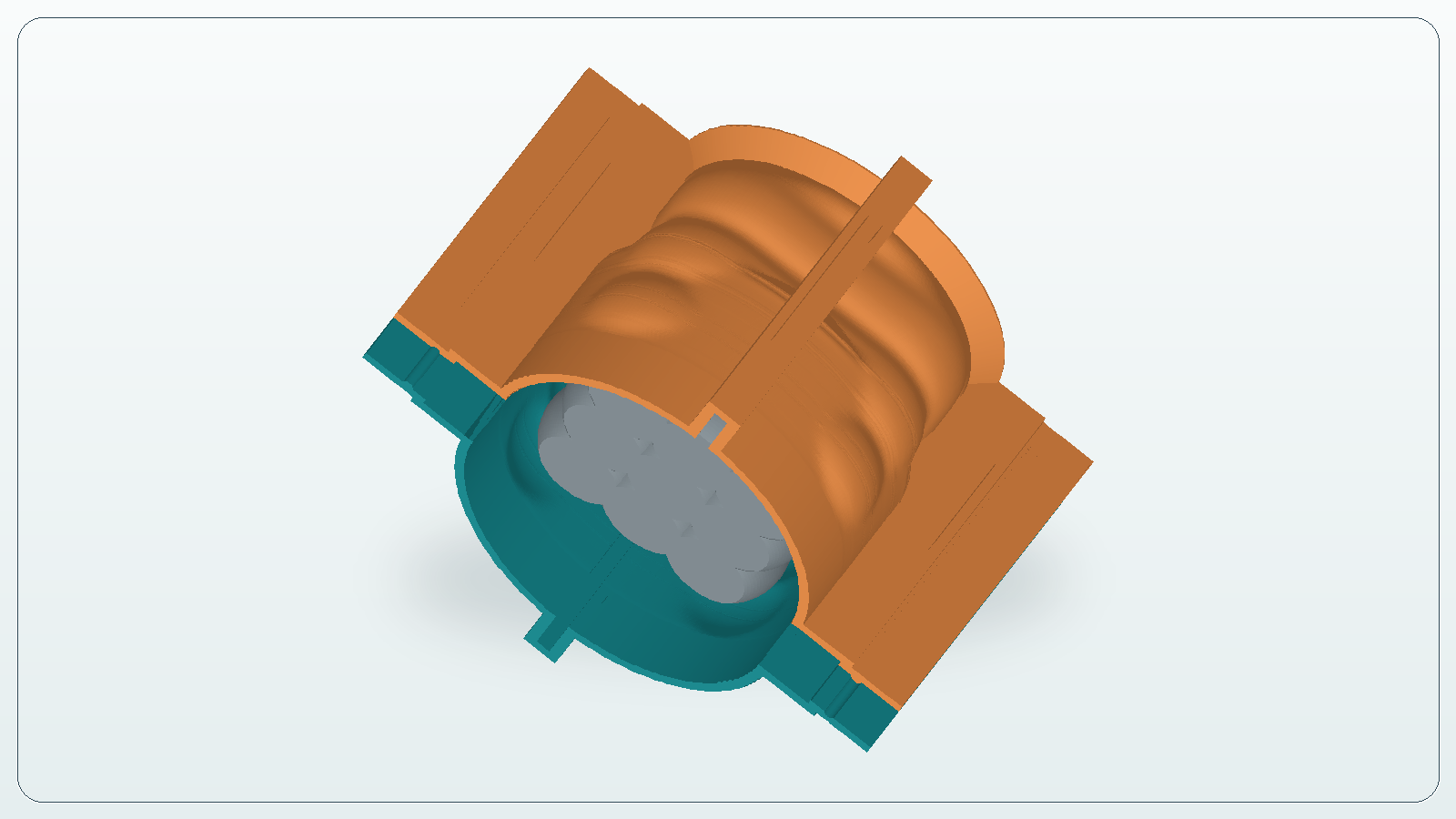
At this stage, check the quality of the result, not just the fact that something was generated. Look at how the walls follow the model, whether they obviously intersect the source STL, whether thin areas appeared, and whether the sections can open after pouring.
The bottom is built as a separate part. The export can include the bottom with the figure or the bottom as a separate part. That is useful because different shops prepare prints differently: some prefer a combined assembly, while others need to control each printable surface separately.

In this example, the footprint is simple and almost elliptical. That works for this candle: there are no long thin protrusions and no details that extend far to the side. If the model had a handle, a hook, or a thin side feature, the bottom and wall sections would need closer inspection.
This is where printable silicone mold formwork differs from a simple box around the model. A plain box usually increases silicone consumption and does not help reveal parting-line issues in advance. STL-based printable formwork should solve the task more precisely: keep silicone where it is needed and leave a clear assembly path.
Before the slicer
After the build, do not send the STL or 3MF files straight to print. The slicer is the last check before plastic, and it often shows problems that are easy to miss in a 3D preview.
Before printing, check that:
- the bottom is clearly oriented and does not conflict with the model;
- the walls do not intersect the source STL;
- the sections can separate after pouring without damaging the silicone;
- the printed parts have enough thickness, and the perimeter count in the slicer matches the expected wall.
It is also worth checking the first layer, seam position, infill, and print time. Decorative surface quality is not always critical for formwork, but predictable geometry is. If a wall prints with a gap, the bottom warps, or the sections do not meet well, the issue will show up during pouring.
For PLA and PETG, dimensional stability and low deformation are usually more important than appearance. Resin printing adds another topic: compatibility with silicone and cure inhibition risk. That is not a CraftMold generation issue, but it is part of the real process. If silicone does not cure near the master model or printed part, the cause may be the material, washing, post-curing, or release agent.
Common mistakes
The first mistake is taking any STL and expecting the service to turn it into a perfect mold setup. If the model has no usable bottom, broken geometry, or obvious hard undercuts, fix the source file first.
The second mistake is making the silicone thickness too small to save material. Saving 10-20 grams can ruin the whole mold if it tears or deforms noticeably during use.
The third mistake is ignoring release. The formwork may look fine on screen, but if the sections cannot be separated after pouring without damaging the mold, the parting line is wrong.
The fourth mistake is printing without checking scale. STL files do not always carry the intended units clearly. If the candle should be 60 mm but appears as 6 mm or 600 mm in the slicer, catch that before printing.
What CraftMold gives you
In this workflow, CraftMold does not cover the entire silicone casting process. It covers one specific step: preparing printable formwork from an STL. The user uploads a model, chooses the bottom plane, sets parameters, reviews the result, and downloads files for 3D printing.
The output is a set of parts: bottom, wall sections, and STL or 3MF export. The production work still remains: printing, surface preparation, assembly, sealing, silicone selection, pouring, and demolding.
For small candles, figures, master models, and pilot batches, this saves time. You do not need to rebuild a box in CAD every time, adjust walls manually, recalculate clearances, and rethink the parting line from scratch. The result still needs human review: before printing, check the geometry, assembly, and the limits of your specific model.
In short: for a suitable STL model, CraftMold helps prepare silicone mold formwork, check it before printing, and export clear files for the slicer.
Check your own STL
If the model has a suitable flat bottom, open CraftMold, upload the file, choose the working plane, and build printable formwork parts.
Access is currently available by promo code.